Example

The WnS process is shown using the example of the reference test complex of haematopoetic cell kinase (HCK, target, in green) and 1-ter-butyl-3-p-tolyl-1H-pyrazolo[3,4-D]pyrimidin-4-ylamine (PP1, ligand, in red)

Wrapper

Steps Download files
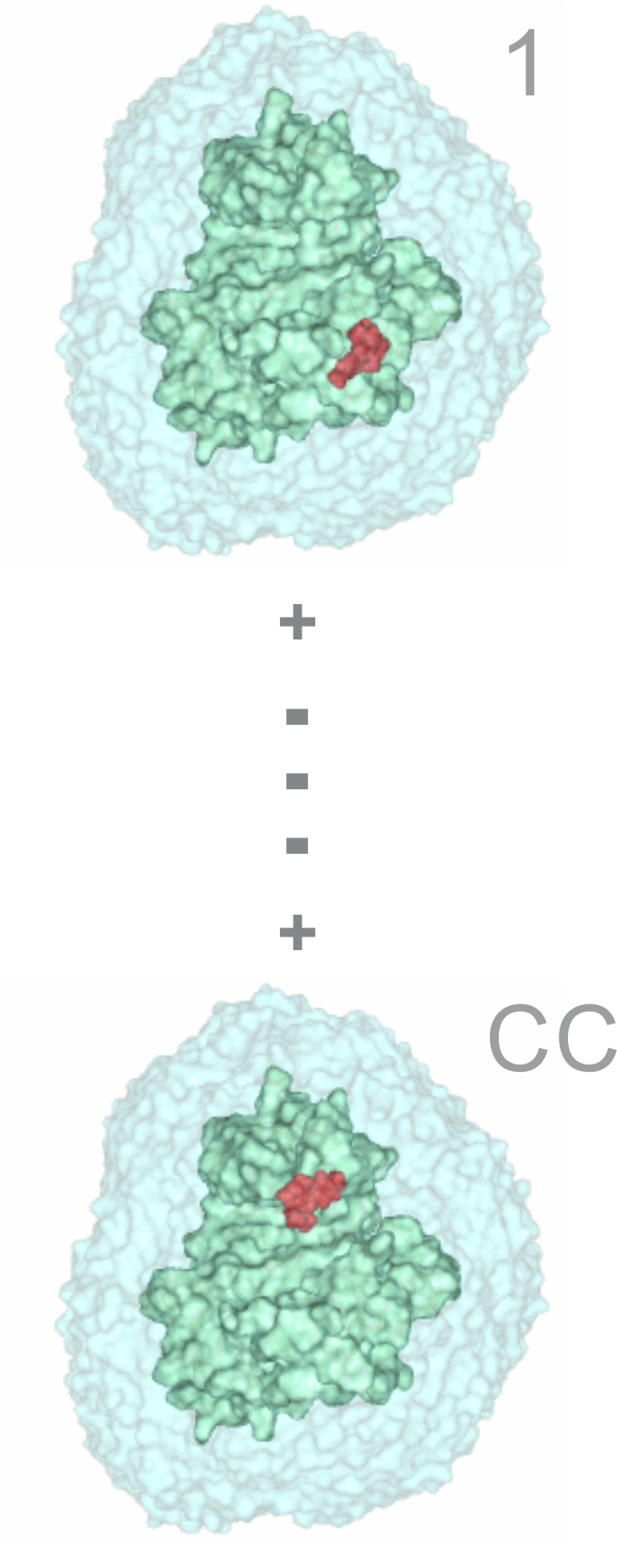
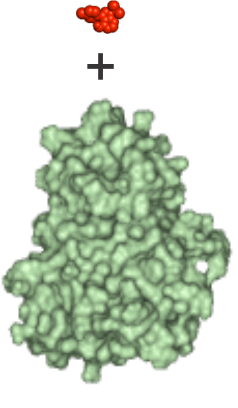
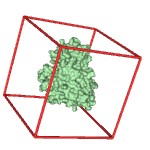
1) Inputs
Structures of the energy-minimized ligand (red) and apo target (green) molecules in Protein Databank (*.pdb) format
Input files
1qcf_ligand.pdb
1qcf_target.pdb
2) Pre-wrapper
2a) Generation of *.pdbqt files with partial charges and atom types. Setting up parameter files for calculation of grid maps (*.gpf) and docking (*.dpf)
2b) The docking box covers the entire target surface (red box, blind docking mode)
2c) Modification of the AD4_parameters.dat file (need to be done only once before the first wrapping cycle)
Generated files
1qcf_ligand.pdbqt
1qcf_target.pdbqt
1qcf_target.gpf
1qcf_target.dpf

Modified AutoDock files

AD4_parameters.dat
autocomm.h
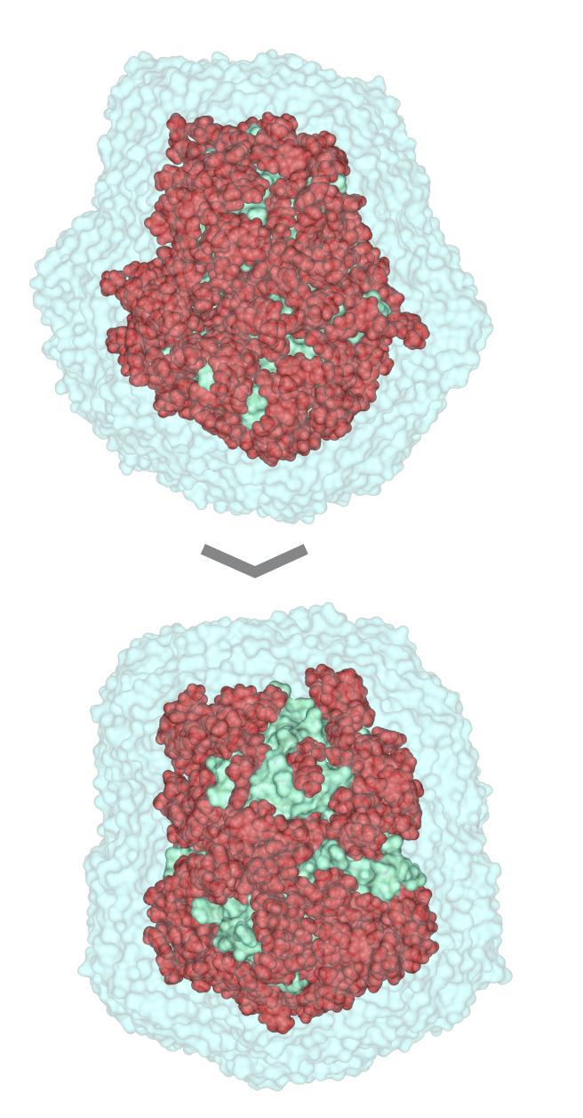
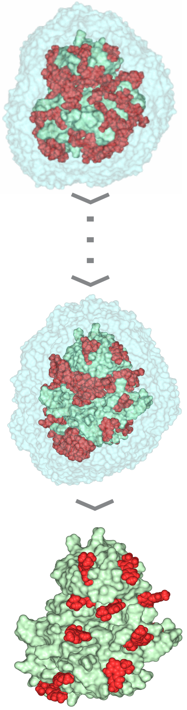
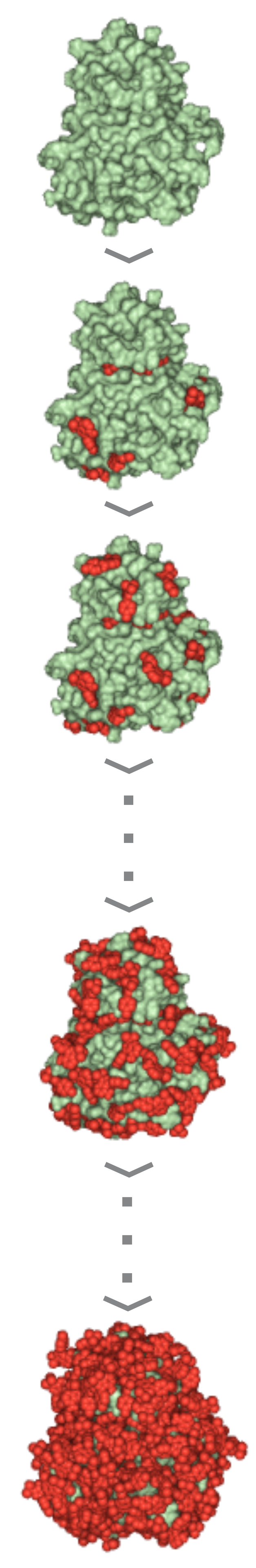
3) Wrapper cycle 1
3a) Grid maps (*.map) and additional files (*.glg, *.fld, *.xyz) are produced by Autogrid 4.2
3b) Docking log file (*.dlg) is produced by AutoDock 4.2. 100 blind docking runs per cycle are performed
3c) The *.dlg file is used as input by program Wrp, which first ranks and clusters the docked ligand conformations. The results are reported in a *.sta file
3d) New atom types (YY, LL) of excluded atoms are assigned by wrp. The corresponding *.YY.map and *.LL.map files are generated before the cycle. The resulted *.wrp.pdbqt file contains the docked ligand copies (cluster representatives)
3e) Available free Accessible Surface Area (ASA) is calculated by Msroll
3f) Wrapping ends if ASA ≤ 1 % or the interaction energy value of any cluster representant in the cycle is ≥ 0 kcal/mol. Otherwise, the *.wrp.pdbqt file is forwarded to the next cycle

4) Wrapper cycles 2-16
The process described at Cycle 1 is repeated in consecutive cycles.
Wrapping will end if a criterion of Point 3f is met.
The complete Wrapping process with all files of the 16 wrapping cycles can be downloaded in a single package (O_1qcf_wrp.tgz)
Autogrid 4.2 outputs
1qcf_target.YY.map.gz
1qcf_target.LL.map.gz
1qcf_target.glg
etc_grid.tgz

AutoDock 4.2 output

1qcf_1.dlg

Gromacs output (ver. 1.1)

O_1qcf_1_ASA_free.log

Msroll output (ver. 1.0)

O_1qcf_1_ASA_free.log

Wrp outputs

O_1qcf_1.log
O_1qcf_1_input_t.pdb
O_1qcf_1_wrp.sta
O_1qcf_1_wrp.pdbqt
etc_wrp.tgz

Wrapper outputs (Cycles 1-16)

O_1qcf_wrp.tgz
5) Trimming
After the last (16th) wrapping cycle a trimming step is involved to remove ligand copies positioned far from the target surface.
The *trm.pdb file contains the target structure wrapped in a monolayer of N=143 ligand copies and can be used in Shaker.
Input files
1qcf_16_wrp.pdbqt
1qcf_ligand_template.pdb
1qcf_ligand_template.pdbqt

Output file

O_1qcf_16_wrp.log
O_1qcf_16_wrp_trm.pdb


Shaker

Steps Download files
6) Molecular dynamics simulation with position restraints applied on the backbone of the target protein (MDB)
The target-ligandN (N=143) complex from the Wrapper step (O_1qcf_16_wrp_trm.pdb) is handled in a single MDB simulation to remove a 25 % of the initial ligand copies
6a) The complex is placed in a simulation box, hydrated, and equipped with neutralizing ions
6b) Energy minimization involves steepest descend (st) and conjugate gradient (cg) runs
6c) The energy minimized complex is subjected to a 5-ns-long MDB simulation with restraints applied on the backbone of the target protein. The resulted trajectory is stored in a portable, compressed file (*.xtc) containing spatial coordinates of all atoms of all frames. The trajectories can be further processed by GROMACS tools using the corresponding binary topology (*.tpr) file
Input files
O_1qcf_16_wrp_trm.pdb
em_st.mdp
em_cg.mdp
md_b.mdp

Generated files
posre.itp
O_1qcf_16_wrp_trm_md1.tpr

Output files
O_1qcf_16_wrp_trm_md1.xtc
7) MDB with simulated annealing (MDBSA) and filtering steps
7a) Filtering 1. Migration distances and ligand-target interaction energies are calculated from the trajectories and applied for filtering out loosely bound ligand copies
7b) The remaining ligand copies bound to the target are subjected to energy-minimization, and a 20-ns-long MDBSA (md2)
7c) Filtering 2. Migration distances and ligand-target interaction energies are calculated from the trajectories and applied for filtering out loosely bound ligand copies
7d) The remaining ligand copies bound to the target are subjected to energy-minimization, and a 20-ns-long MDBSA (md3)
7e) Filtering 3. Migration distances and ligand-target interaction energies are calculated from the trajectories and applied for filtering out loosely bound ligand copies
7f) Clustering and ranking. As the elimination rate (ER) is ≥ 0.75, further MDBSA & filtering steps are not necessary. Cluster representatives are collected in a final output (*_flt3_cls.pdb), and ranked by their interaction energies
Input files
O_1qcf_16_wrp_trm_md1_flt1.pdb
O_1qcf_16_wrp_trm_md2_flt2.pdb
em_st.mdp
em_cg.mdp
md_bsa.mdp

Generated files
posre.itp
O_1qcf_16_wrp_trm_md2.tpr
O_1qcf_16_wrp_trm_md3.tpr

Output files
O_1qcf_16_wrp_trm_md2.xtc
O_1qcf_16_wrp_trm_md3.xtc
O_1qcf_16_wrp_trm_md3_flt3_cls.pdb
8) Refinements with flexible MD (MDF)
Target-ligand complexes are created by splitting the CC=12 cluster representatives. Each complex contains one copy of the target structure and one cluster representative. The complexes are subjected to separate 20-ns-long MDF simulations where no restraints were applied. Example files for the first cluster are shown, and output files of all clusters are provided in a compressed library (*.tgz)
Input files
O_1qcf_16_wrp_trm_md3_flt3_1.pdb
em_st.mdp
em_cg.mdp
md_f.mdp

Generated files
O_1qcf_16_wrp_trm_md3_flt3_1.tpr

Output files
O_1qcf_16_wrp_trm_md3_flt3_1.xtc
O_1qcf_16_wrp_trm_md3_flt3.tgz